

Position
In the world of mechanical engineering and manufacturing, Geometric Dimensioning and Tolerancing (GD&T) is a cornerstone for ensuring that parts meet design intent and function properly. Among the most critical concepts in GD&T is position. This article unpacks what position is, why it matters, and how to interpret and apply it effectively in your designs.
Contents
1What is Position in GD&T?
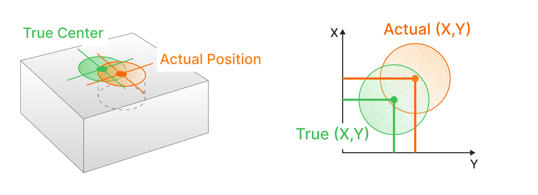
Position is a location-based tolerance that controls how far a feature (like a hole, slot, or pin) can deviate from its exact, theoretically perfect location as specified in a design. Position is often used for locating features relative to datums and is particularly essential when multiple features must align or fit together in an assembly.
Unlike simpler tolerances (e.g., linear tolerances like ±0.05), position considers not just the distance from a nominal point but also the permissible variations in 3D space, relative to reference datums. This makes it a powerful tool for complex assemblies where precision and functionality are paramount.
2Why is Position Important?
Position tolerancing is critical because:
- It Ensures Fit and Functionality: For example, holes that must align for a fastener to fix corresponding components. Positional tolerance ensures they do so reliably, even with minor manufacturing variations.
- It Reduces Ambiguity: Position eliminates the “stacking” of tolerances often associated with linear dimensions by defining acceptable limits in 3D space.
- It Balances Precision and Manufacturability: Position provides flexibility by allowing parts to meet functional requirements without over-tightening tolerances, which can increase manufacturing costs.
3How is Position Represented?
Position is represented in a feature control frame (FCF), which typically looks like this:
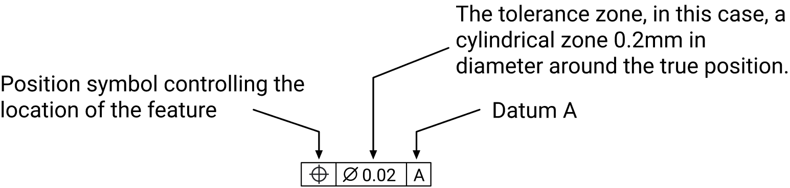
Here’s what each element means:
- Position: The geometric characteristic being controlled.
- Ø0.02: The tolerance zone, in this case, a cylindrical zone 0.02mm in diameter around the true position.
- A: The datum that define the part’s reference coordinate system.
4Key Concepts of Position
- Position applies to any feature of size, such as holes, slots, bosses, tabs, or spheres, and controls the central elements (axes or center planes) of these features. While Position is used to locate and tolerance these size features, locating surfaces should be controlled using the Profile tolerance instead.
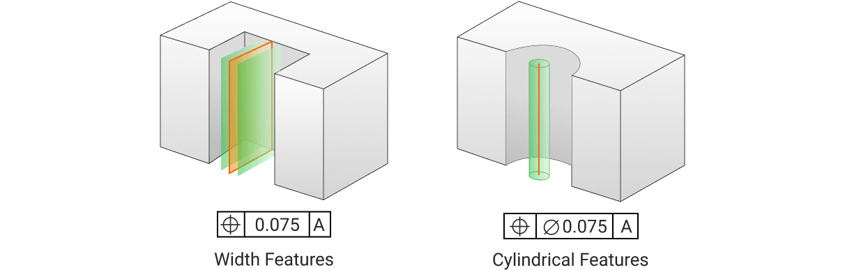
- Tolerance Zone: For a hole or pin, the position tolerance defines a cylindrical zone within which the axis or centerline of the feature must lie. For rectangular features, it could define a rectangular or parallelepiped zone as seen in the image above.
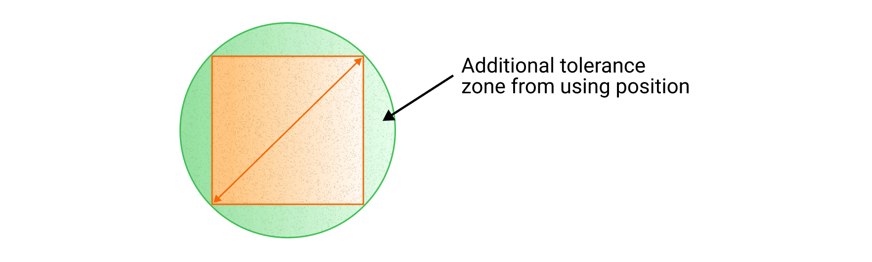
- Position tolerances can be specified in two ways: as linear distances in the X and Y directions or, more commonly, using the diameter symbol (Ø) to indicate a cylindrical tolerance zone. When specified as linear distances, the tolerance zone forms a square, allowing permissible movement within the X and Y limits. As seen below, by using the diameter symbol to create a cylindrical tolerance zone, you maximize the allowable variation uniformly in all directions around the true position, making it the preferred method for most applications.
- MMC (Maximum Material Condition) and LMC (Least Material Condition):
- MMC adds functional tolerance by allowing more deviation when the feature is at its largest permissible size (e.g., a smaller hole).
- LMC is the opposite, deviation is permissible when the feature is at its smallest permissible size.
5Interpreting a Position Tolerance

Imagine a part with a hole that must align with a corresponding hole on a mating component. The drawing specifies a position tolerance of Ø0.075 relative to datum A. This means:
- Each hole’s center must lie within a cylindrical tolerance zone 0.075mm in diameter.
- The tolerance zone is positioned relative to the datums to ensure the holes align perfectly with the mating part.
6Tips for Applying Position Tolerancing
- Use Datums Wisely: Carefully select datums to reflect functional requirements. Good datum selection ensures stability and repeatability during inspection and assembly.
- Consider Functional Needs: Choose position tolerances that balance precision with manufacturability. Too tight a tolerance can drive up costs without adding value.
- Leverage MMC/LMC: Utilize MMC or LMC modifiers where applicable to maximize allowable deviations without compromising function.
- Inspect with the Right Tools: Position tolerances often require specialized inspection methods, such as Coordinate Measuring Machines (CMMs) or functional gages.
7Common Applications of Position Tolerancing
- Bolt Patterns: Ensures the holes for fasteners align correctly, critical in flanges, engine components, and structural assemblies.
- Mating Features: Aligns pins and holes for precise assembly.
- Connector Interfaces: Ensures electrical or fluid connectors fit within tight tolerances for reliable operation.
8Practical Example
Let’s walk through a simple example:
A part has a hole that needs to mate with a pin on another component. The drawing specifies:
- Hole size: Ø10.0 ±0.1
- Position: Ø0.2 MMC relative to datums A, B, and C.
If the hole is manufactured at its MMC size of Ø9.9, the center can deviate up to 0.2mm. If the hole is at its LMC size of Ø10.1, the additional material gives even more positional tolerance, ensuring manufacturability and cost efficiency.
9Conclusion
The GD&T concept of position is an indispensable tool in modern mechanical design and manufacturing. By specifying a tolerance zone for feature location, position ensures functionality, reduces ambiguity, and optimizes cost and manufacturability. Whether you’re designing a simple bracket or a complex aerospace assembly, mastering position tolerancing will elevate your engineering skills and ensure better outcomes for your projects.
Got a tricky GD&T question? Feel free to reach out, we’re here to simplify the complex and empower your designs!
Get the next one.
New notes go out to the Drafter newsletter. A free account signs you up, and opens the calculators and cheat sheets in the toolbox while you wait.
Create a free accountKeep reading
 GD&TAngularityAngularity in GD&T is a symbol that defines the orientation of one feature relative to another at a specified angle within a 3D tolerance zone.Surface control shown to left. Angularity can also apply to a FOS where the derived median plane or line is controlled.
 GD&TParallelismParallelism in GD&T ensures that a referenced feature maintains a parallel orientation to a specified datum surface or line within a 3D tolerance zone.
 GD&TStraightnessStraightness is one of the most fundamental form tolerances. It is used to ensure that a feature, such as a surface or an axis, conforms to a specific linear path without deviations. Straightness is crucial for parts where linear precision is vital for fit, function, and performance.