What is Straightness in GD&T?
Straightness is a geometric tolerance that controls how much a feature can deviate from an ideal straight line. It applies to two different contexts:
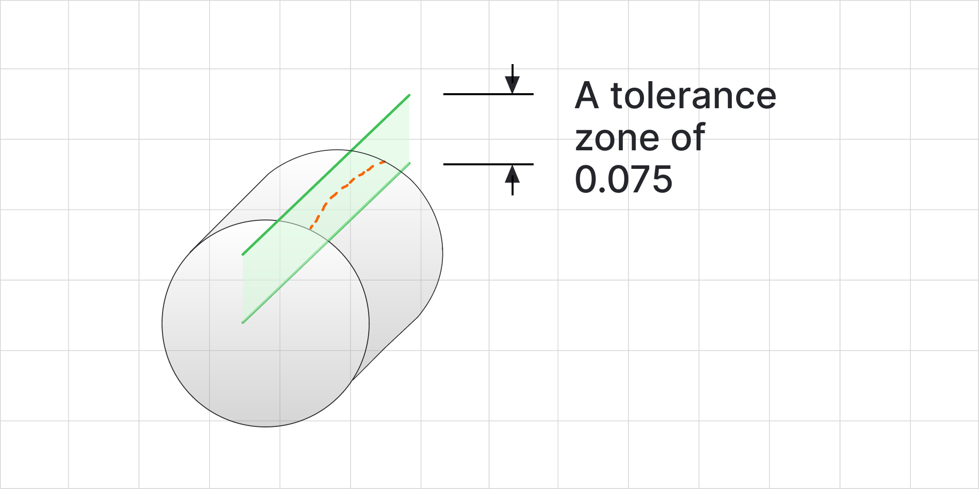
- Surface Straightness: Controls the straightness of a line element on a surface.
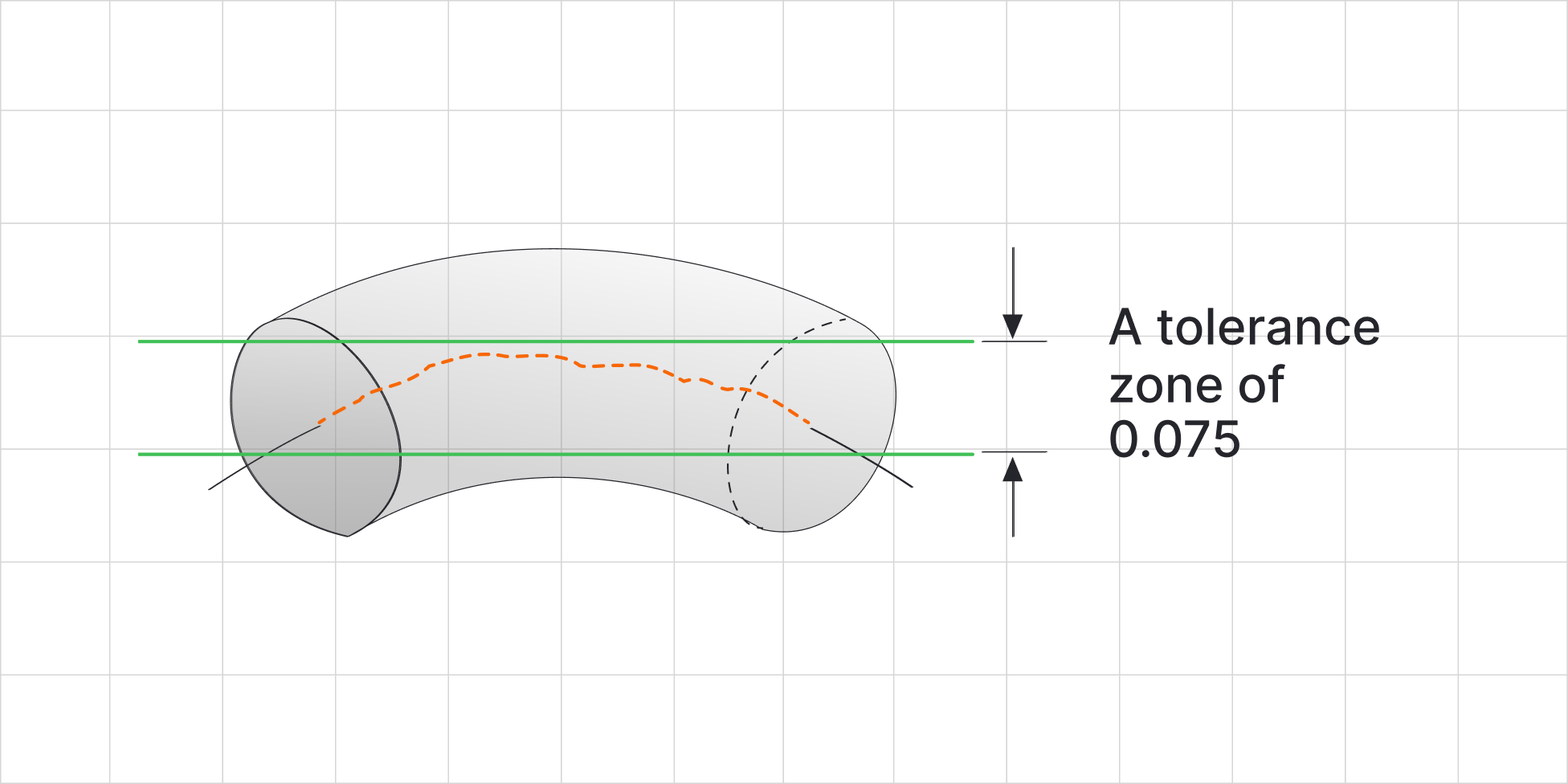
- Axis Straightness: Controls the straightness of the axis of a feature of size, such as a cylindrical hole or shaft.
Straightness is a form tolerance, meaning it applies to individual features without reference to any datums.
Types of Straightness
Surface Straightness
- Definition: Ensures that a specific line element on a surface remains within a tolerance zone around an ideal straight line.
- Application: Used to control the flatness of a surface in a specific direction, often for sealing surfaces, guide rails, or sliding components.
- Tolerance Zone: A two-dimensional zone, usually defined by two parallel lines spaced apart by the tolerance value.
Axis Straightness
- Definition: Ensures that the axis of a cylindrical or other feature of size lies within a cylindrical tolerance zone.
- Application: Commonly used for shafts, holes, or pins to ensure proper fit and alignment in assemblies.
- Tolerance Zone: A three-dimensional cylindrical zone within which the axis must remain.
How Straightness is Represented
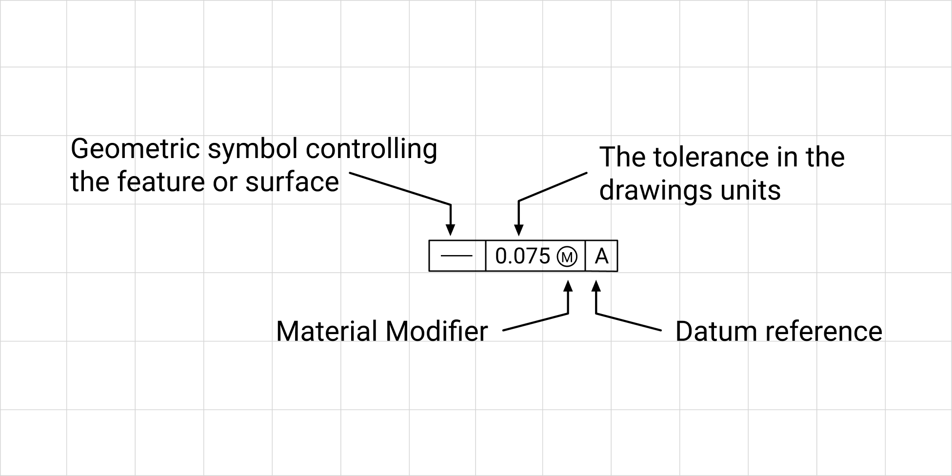
Straightness is specified in the feature control frame, using the straightness symbol (a horizontal line).
Example Feature Control Frame
Interpretation:
- The feature must remain within a straightness tolerance of 0.05 mm.
When controlling an axis using straightness, the tolerance can be paired with material condition modifiers such as Maximum Material Condition (MMC) or Least Material Condition (LMC), which affect how the tolerance is applied based on the feature’s actual size.
Material condition modifiers should not be used when controlling surface straightness
Understanding Material Condition Modifiers with Axis Straightness
- Maximum Material Condition (MMC): Provides additional tolerance when the feature is at its maximum material condition (e.g., smallest hole or largest shaft). This is useful for features that mate with others, as it ensures proper assembly while allowing for manufacturing variability.
- Least Material Condition (LMC): Used less frequently, it provides tolerance when the feature is at its least material condition (e.g., largest hole or smallest shaft).
Practical Applications of Straightness
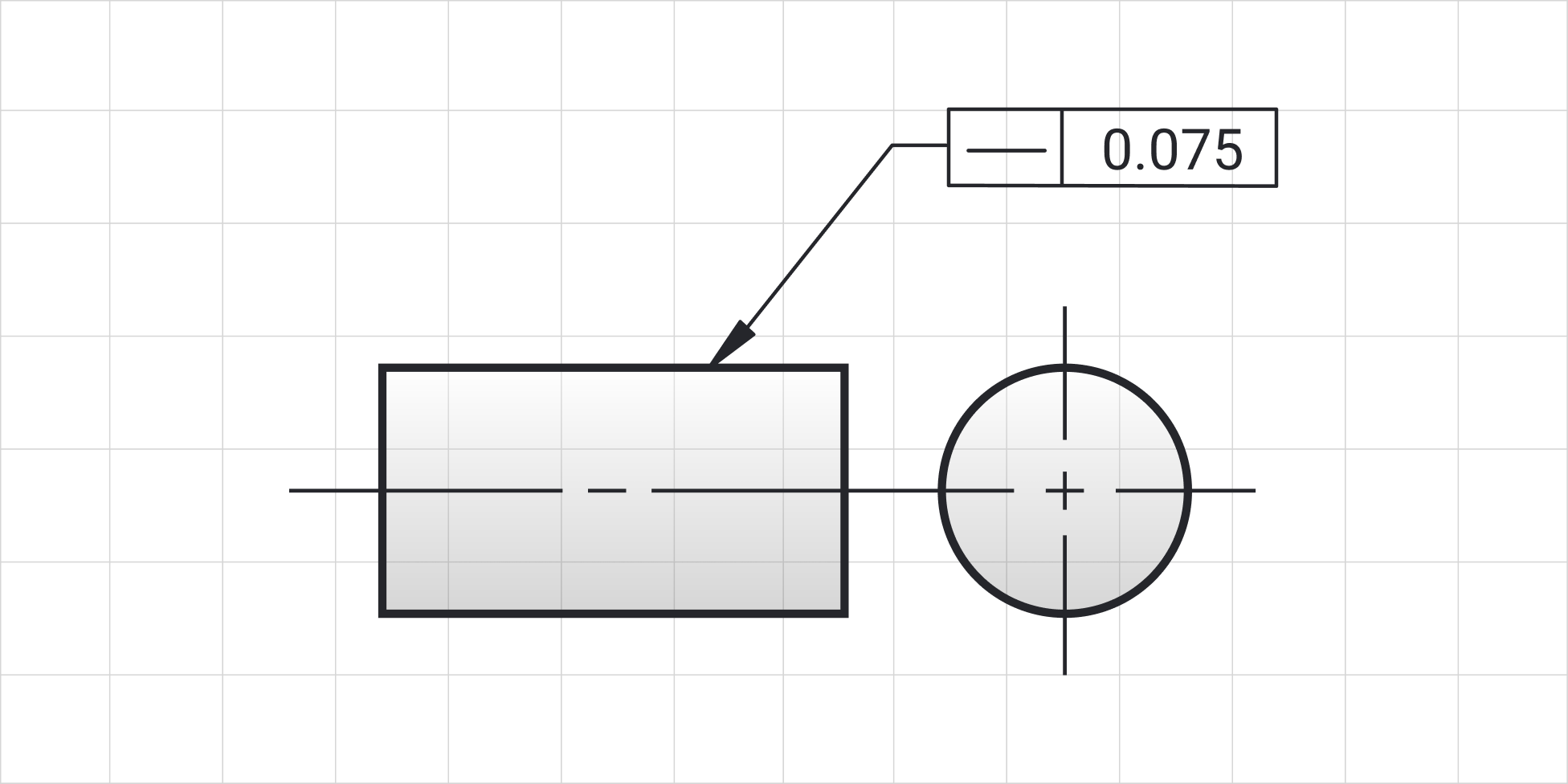
- Surface Straightness
- Example: A guide rail must have a straight edge to ensure smooth motion for a sliding part. Surface straightness ensures the edge remains linear within the specified tolerance.
- Axis Straightness
- Example: A cylindrical shaft must have a straight axis to fit properly into a bearing. Axis straightness ensures the shaft’s axis does not deviate from its ideal path, preventing vibration and misalignment.
Inspection of Straightness
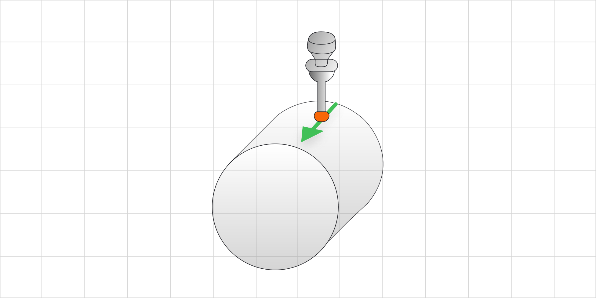
Inspecting Surface Straightness
- Tools: Surface straightness is often measured using a dial indicator and a straight edge, or more precisely with Coordinate Measuring Machines (CMMs).
- Process: The dial indicator is run along the surface, and the total indicator reading (TIR) is checked against the specified tolerance.
Inspecting Axis Straightness
- Tools: Axis straightness is typically measured using a CMM, a dial bore gage (for internal features), or specialized fixturing.
- Process: The part is aligned with the measurement system, and the deviations of the axis from its ideal position are recorded.
Relationship with Other GD&T Controls
Straightness is closely related to and often used in conjunction with other GD&T tolerances:
- Flatness: While flatness controls the overall surface, straightness controls individual line elements on that surface.
- Cylindricity: Cylindricity combines straightness, circularity, and taper to control the entire surface of a cylinder.
- Position: Straightness of an axis is often inspected as part of a position tolerance to ensure alignment in assemblies.
Benefits of Specifying Straightness
- Enhanced Precision: Ensures parts fit together correctly, improving the functionality of assemblies.
- Reduced Wear: Minimizes friction and uneven contact in moving components.
- Improved Quality Control: Provides clear criteria for inspecting and verifying parts.
- Manufacturing Flexibility: Using material condition modifiers allows for tighter tolerances while maintaining manufacturability.
Practical Example
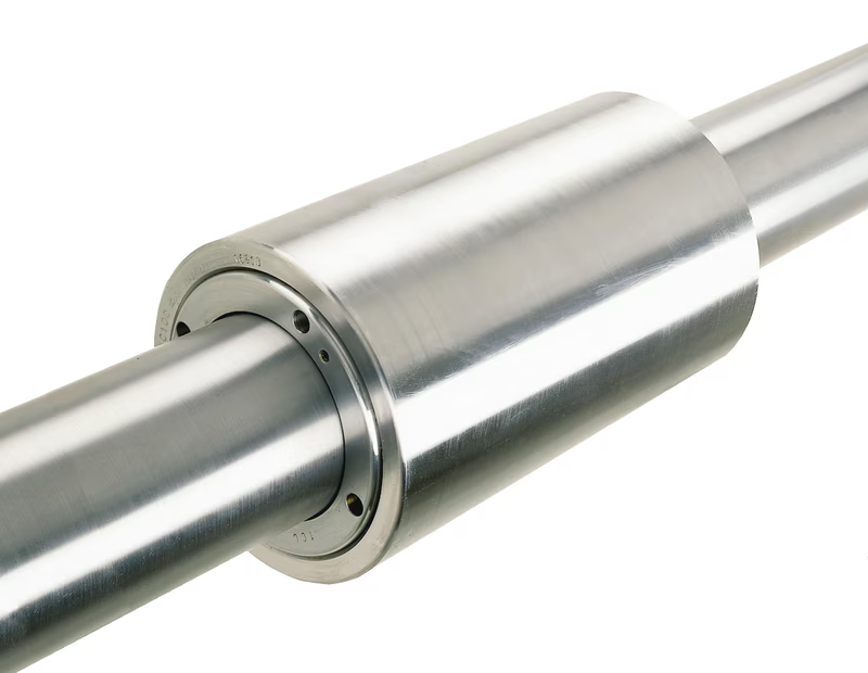
Scenario: Designing a sliding mechanism where a shaft moves within a sleeve.
- Requirement: The shaft must be straight to ensure smooth motion without binding.
Solution:
- Specify axis straightness of Ø0.02mm relative to the shaft’s ideal centerline.
- Use MMC to maximize tolerance when the shaft is at its largest permissible diameter.
- Outcome: The mechanism operates smoothly, with no binding or misalignment.
Tips for Using Straightness
- Choose the Right Type: Use surface straightness for flat surfaces and axis straightness for cylindrical features.
- Specify Appropriate Tolerances: Tighten tolerances only as much as necessary for functionality to avoid increasing manufacturing costs.
- Leverage Modifiers: Use MMC or LMC to provide flexibility in manufacturing without compromising functionality.
- Plan for Inspection: Ensure that the necessary tools and techniques are available to measure straightness accurately.
Straightness is a fundamental GD&T control that ensures parts maintain their intended form and function. Whether applied to a surface or an axis, straightness tolerances play a vital role in achieving precision, reducing wear, and improving the performance of assemblies. By understanding how to specify and inspect straightness effectively, engineers can create designs that meet the highest standards of quality and reliability.
If you have questions about applying straightness or other GD&T principles to your designs, feel free to reach out—we’re here to help you achieve precision and success!


