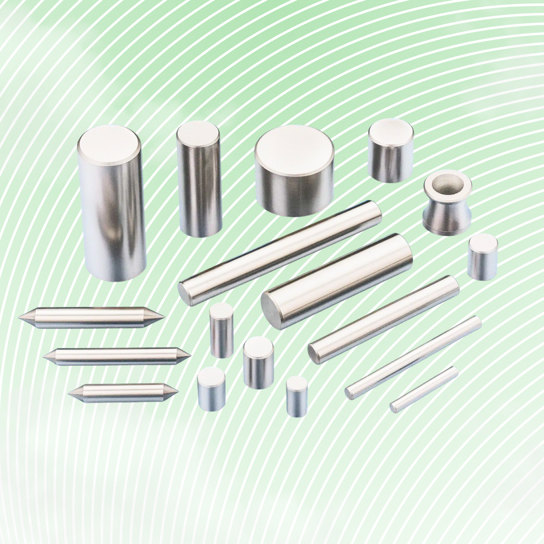
What is GD&T
Geometric Dimensioning and Tolerancing (GD&T) is a symbolic language used in engineering drawings to define the allowable variations in the geometry of parts and assemblies. GD&T standardizes communication of functional requirements, ensuring parts are manufactured, fit, and function correctly within acceptable limits of your Design Intent.
In today's globalized and competitive manufacturing environment, the ability to produce high-quality parts efficiently and consistently is more important than ever. GD&T plays a crucial role in this by providing a standardized way to communicate design intent. Whether you're working on a simple part or a complex assembly, GD&T ensures that every detail of your design can be clearly understood by everyone involved in the production process.
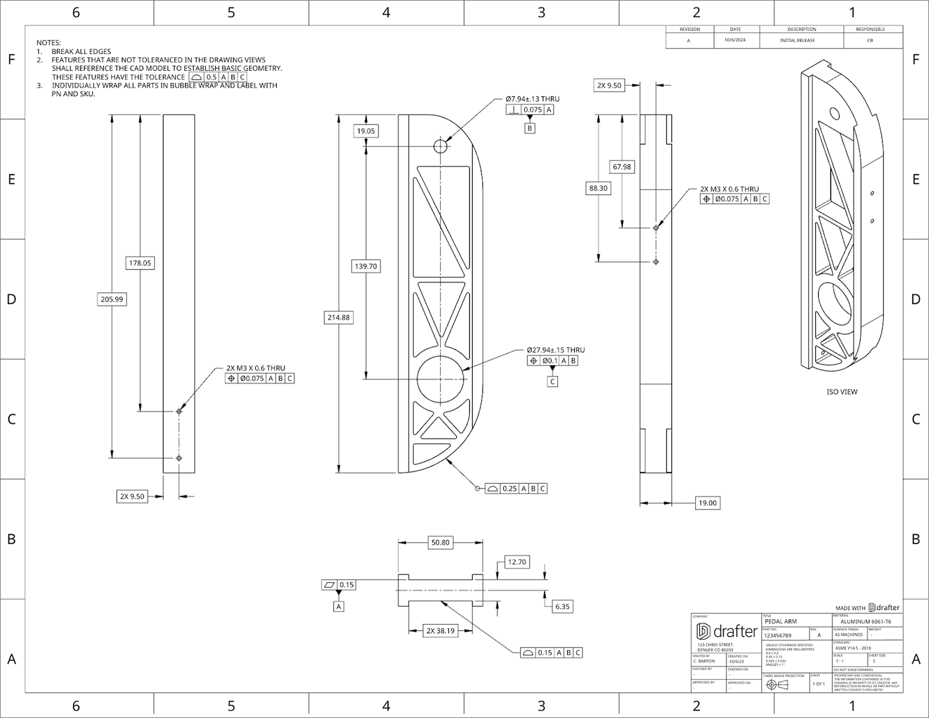
What is Design Intent?
Design intent refers to the purpose and functional requirements that a designer aims to achieve in a product or part. It encompasses the desired performance, aesthetics, manufacturability, and usability of the design, guiding decisions throughout the development process to ensure that the final product meets its intended goals. Design intent also ensures that all design elements work together cohesively and that any variations in manufacturing still result in a functional and acceptable product.
Why GD&T Matters
In 1990, NASA launched the Hubble Space Telescope, a marvel of engineering that promised to give us crystal-clear images of the universe. But when it started sending back photos, there was a big problem—the images were blurry. This wasn’t just a slight blur; they were completely unusable, causing an uproar after years of work and billions of dollars spent.

So what went wrong? The culprit: a tiny manufacturing error in the telescope’s main mirror. It was off by just 2 microns—that’s 1/50th the thickness of a human hair. While that sounds ridiculously small, in the world of high-precision optics, it was a disaster. The mirror wasn’t positioned exactly as it should’ve been because the tolerances for how it needed to be manufactured and assembled weren’t properly followed.
In engineering terms, the GD&T (Geometric Dimensioning and Tolerancing) was off. The features of the mirror weren’t controlled correctly, and that tiny misalignment ended up ruining the functionality of the entire telescope. The result? NASA had to spend millions more dollars and launch a whole new mission just to fix the problem by installing corrective optics.
Thankfully, after the repair, Hubble went on to become one of the most successful space telescopes ever. But this story is a perfect reminder of how crucial GD&T is in engineering. Even the smallest mistake in how we control and define tolerances can lead to major setbacks, extra costs, and delays. It’s not just about designing parts; it’s about ensuring those parts work together exactly as intended.
GD&T is more than just a set of symbols and rules—it's a powerful tool for ensuring that your designs are manufactured correctly, function as intended, and can be produced at scale. By using GD&T, engineers can communicate their design intent more effectively, leading to better products, fewer production issues, and lower costs. Just remember: a few microns almost doomed one of the most important scientific tools in history.
Breaking GD&T down
Every assembly is made up of different parts that work together to serve a specific purpose. As an engineer or manufacturing professional, your goal is to design a system of parts that best achieves this purpose, meets all the design requirements, and does so at the lowest possible cost. The cost is directly tied to how easy the parts are to manufacture and how scalable the production is. This depends on factors like the material used, the process to make it, and the time it takes to produce.
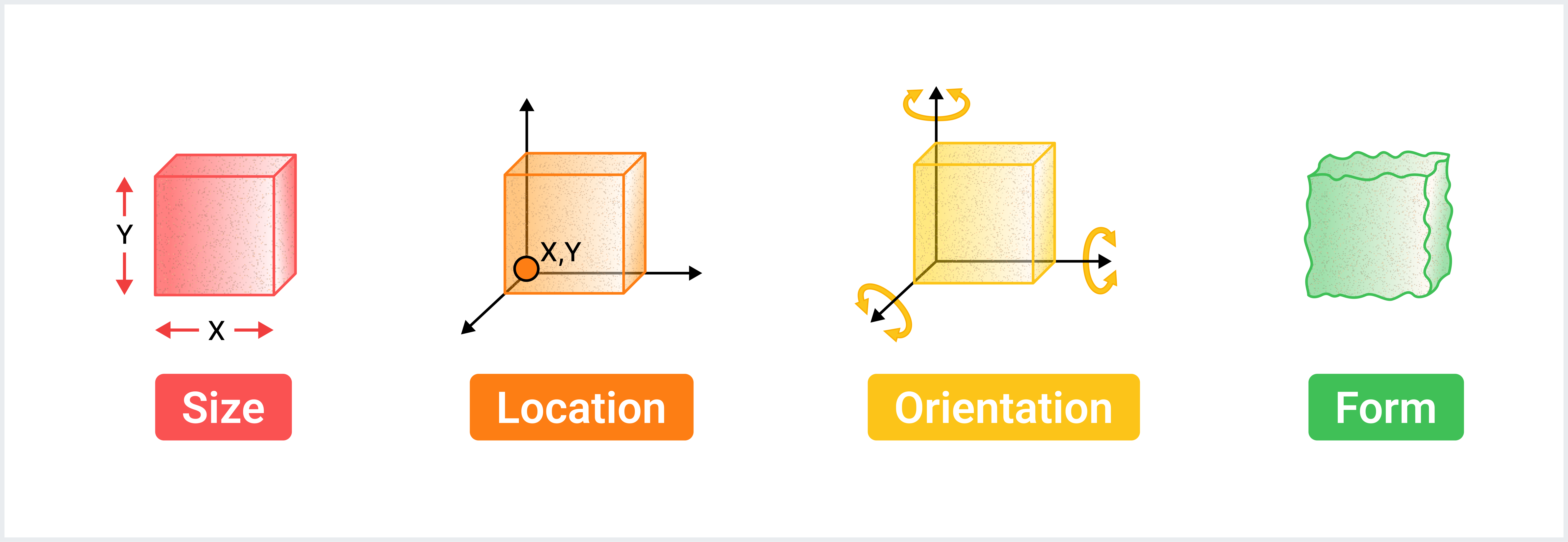
There are two main areas you can adjust to control costs: your design requirements (which influence things like material choice and how strong the parts need to be) and the shape of the parts (geometry). Since each part is made of material and has specific features, these features either serve a function or help the part connect with other components. To ensure the part meets your design goals, engineers use something called GD&T (Geometric Dimensioning and Tolerancing) to carefully define the size, location, orientation and form of these features.
What is being controlled: SLOF (Size, Location, Orientation, Form)
The four categories of control in GD&T follow the SLOF framework:
- Size: This controls the actual dimensions of a part. Size can be defined using a specific value and tolerance range (for example, a part could be 10mm ± 0.1mm). Alternatively, size can be controlled using symbols like Profile, which set limits on the shape and dimensions of a part.
- Location: This defines where a part or feature is in relation to other parts. It ensures that each feature is in the correct spot for the overall assembly to function properly.
- Orientation: This specifies the direction or angle a feature is pointed. For instance, the axis of a hole or a cylindrical surface should be oriented within a certain tolerance. It controls how much the actual axis can deviate from a perfectly theoretical axis while still being functional.
- Form: In the real world, surfaces are never perfectly flat or smooth. Form defines how much imperfection is allowed on a surface or feature while ensuring the part still works as intended. It ensures that these imperfections don’t affect the performance of the part.
Each category plays a key role in making sure parts fit together and function as designed, even with real-world imperfections.
Understanding Datums: Your Reference Points
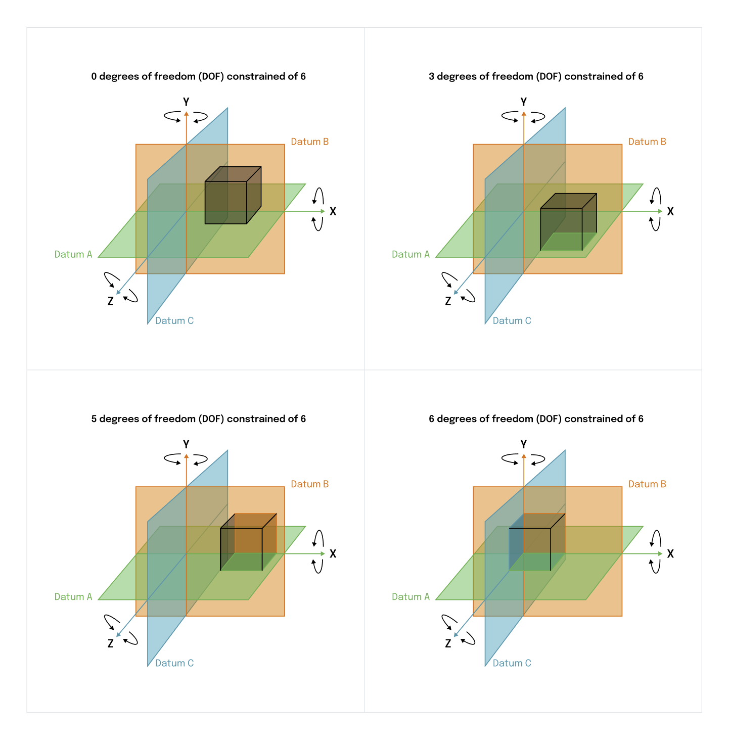
Before diving into reading GD&T symbols, you must understand datums. A Datum Reference Frame (DRF) serves as the reference point for all measurements. It’s essentially a coordinate system that allows the engineer to control the orientation, position, and size of a part.
A DRF is made up of multiple reference surfaces or features, usually marked by letters (A, B, C). These letters correspond to features on the part, such as flat faces, and help define how the part is constrained.
Example of planar datums:
- Datum A might be a large flat face, restricting three degrees of freedom.
- Datum B could be a secondary surface, restricting two more degrees of freedom.
- Datum C might be the final surface or feature, fully constraining all six degrees of freedom.
How to choose datums
We’ll go into more detail later about how to select "datums," but for now, here’s a brief overview of some basic rules:
The best GD&T (Geometric Dimensioning and Tolerancing) is based on the part's function, so a good Datum Reference Frame (DRF) is often guided by how the part is mounted. This creates what’s called the Mounting Datum Reference Frame (MDRF).
When selecting datums, start by choosing surfaces or features that have the largest surface area because they help to "constrain" the part in space. *Constraints* refer to how a part is held or restricted in movement during assembly and use. Think about how the part will be put together and how it needs to stay in place during its operation.
- Datum A should be the largest and most stabilizing surface or feature to hold the part securely.
- Datum B should be the next surface or feature that provides additional stability.
- Datum C may also be needed, depending on how complex the part’s constraints are.
Each datum helps lock the part in place during assembly and ensures it functions properly.
Comments:
- If a part rotates or moves in function, you may not need to constrain all six degrees of freedom.
- You can use a group of features as a datum, but this can complicate referencing in inspection.
Feature Control Frame (FCF): How to Communicate GD&T
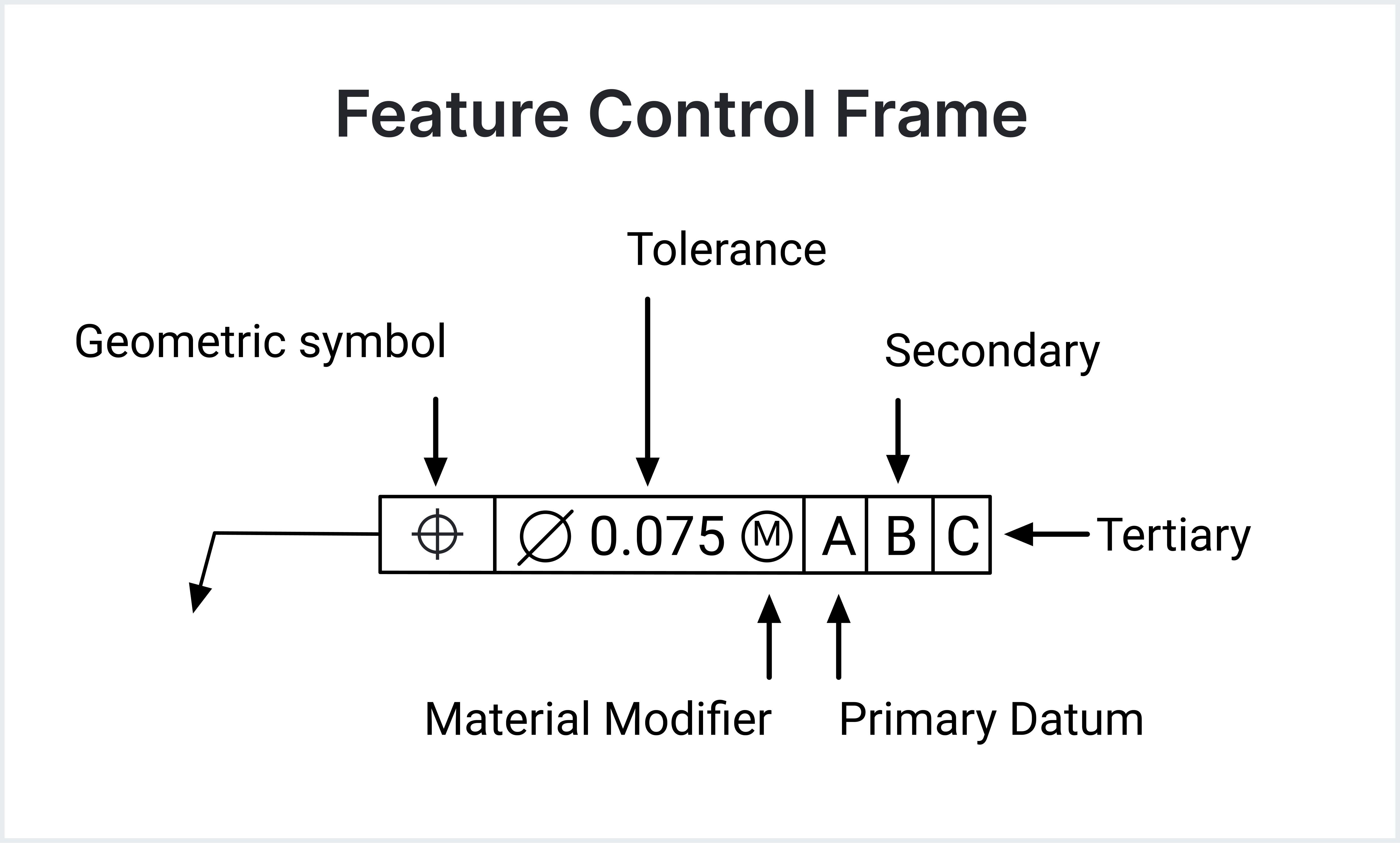
Now we’re getting to the core of reading and writing GD&T—the Feature Control Frame (FCF). The FCF is the box on a drawing that contains all the necessary information for controlling the feature.
Each FCF contains:
- A symbol representing the type of control (flatness, position, etc.).
- A tolerance value specifying the allowable variation.
- The datum reference frame (DRF) showing the reference points used for the measurement.
Symbols and Their Meanings
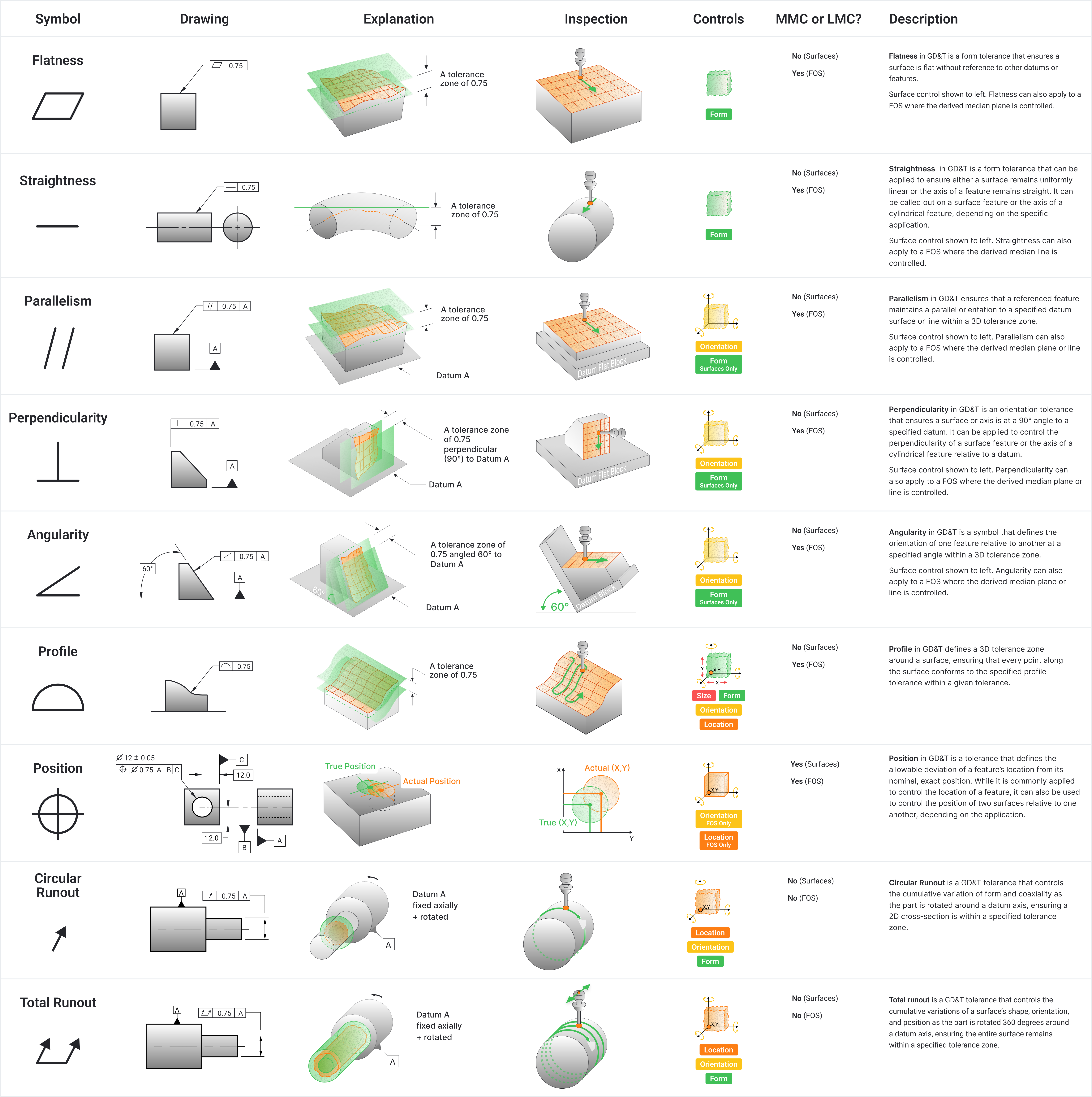
- Flatness: Flatness controls how flat a surface must be. It specifies that all points on the surface must lie within two parallel planes spaced apart by the flatness tolerance value. Flatness is often used for mating surfaces or surfaces that need to slide or rotate against another component.
- Straightness: Straightness controls how straight a line element of a surface or a derived medial line must be. It can apply to both surface elements and the axis of a cylindrical feature. The straightness tolerance zone is a pair of parallel lines for surface elements or a cylindrical zone for an axis.
- Profile of a Surface: Profile of a surface tolerance controls the 3D shape of a surface, ensuring that the entire surface lies within a tolerance zone that follows the true geometric form of the surface. It is often used for aerodynamic surfaces or parts with complex curves.
- Angularity: Angularity controls the angle between a feature and a datum plane or axis, ensuring that the feature lies within a specified angle range. Angularity is critical in components that require precise angles for proper assembly or function.
- Perpendicularity: Perpendicularity ensures that a tolerance zone is exactly 90 degrees to a datum. This tolerance is used to control the orientation of features like holes or mating surfaces, ensuring proper alignment in assemblies.
- Parallelism: Parallelism controls how parallel a feature is relative to a datum. The tolerance zone is a pair of parallel planes or a cylindrical zone within which the feature must lie. Parallelism is crucial for features that must move or fit together without binding.
- Position: Position tolerance controls the exact location of a feature, such as a hole or slot, relative to a datum. The tolerance zone is typically a cylindrical or spherical zone or width within which the centerpoint or axis or centerplane of the feature must lie. Position tolerance is one of the most commonly used GD&T controls because it provides a clear and precise way to ensure proper part fit.
- Total Runout: Total runout controls the variation of a feature’s entire surface as it rotates around a datum axis. This tolerance ensures that the entire surface remains within a cylindrical tolerance zone, accounting for both form and location variations. Total runout is often used for critical features like bearing surfaces.
Basic Dimensions
In GD&T, basic dimensions are theoretically exact values used to define the precise size, location, or orientation of a feature. Unlike other dimensions, basic dimensions don’t have tolerances directly associated with them. Instead, the allowable variation is controlled by the GD&T tolerance symbols, such as position or profile, which define the limits within which the feature must fall. Basic dimensions provide the "ideal" measurements, while GD&T defines how much variation from that ideal is acceptable.
For example, on a drawing, you might use a basic dimension to specify the exact position of a hole relative to a datum (reference point) because that hole needs to align perfectly with another part in an assembly. Another example is the angle between two surfaces; a basic dimension would define the ideal angle (e.g., 45°), while a GD&T control like angularity would specify how much deviation from that angle is acceptable. Basic dimensions are placed wherever precise control is required for functionality, and they work in conjunction with GD&T symbols to control the allowable variation.

What Gets GD&T
So at a very basic level, what should get GD&T? Everything that doesn't mate to air.
Open your assembly that the part lives within and consider the following:
- What surface or feature locates and orients this part in space? OR How is this part mounted in the assembly? This should be your primary datum. If there are a few options, choose the surface or feature with the most surface contact area.
- What other features or surfaces supplement the primary datum to constrain the part in space? These are good options for your secondary and tertiary datums. Remember, always constrain the parts in the quantity of Degrees of Freedom that simulate the function of the part!
- Once you have identified datums, next select every feature that is used to connect to another part. This will usually be holes or external diameters. Each of these should be controlled with a size callout and a feature control frame indicating its locational tolerance.
- Next, choose all surfaces that need to be held to a precise tolerance. This can be used to ensure there is clearance on a tight fitting area, or for an aesthetic surface that needs to be controlled. These will usually be controlled using a profile or Form tolerance in a feature control frame, pointing at the surface.
- Finally, choose all distances that require control because the width either “fits inside something else” or “Something fits inside the distance”. These will require a size tolerance as well as a location tolerance to ensure fit and function.
Using these five steps above, you should be able to capture all your critical features.
Now Let's Give it a Try
Step 1: Introducing the Part and Its Role in the Assembly
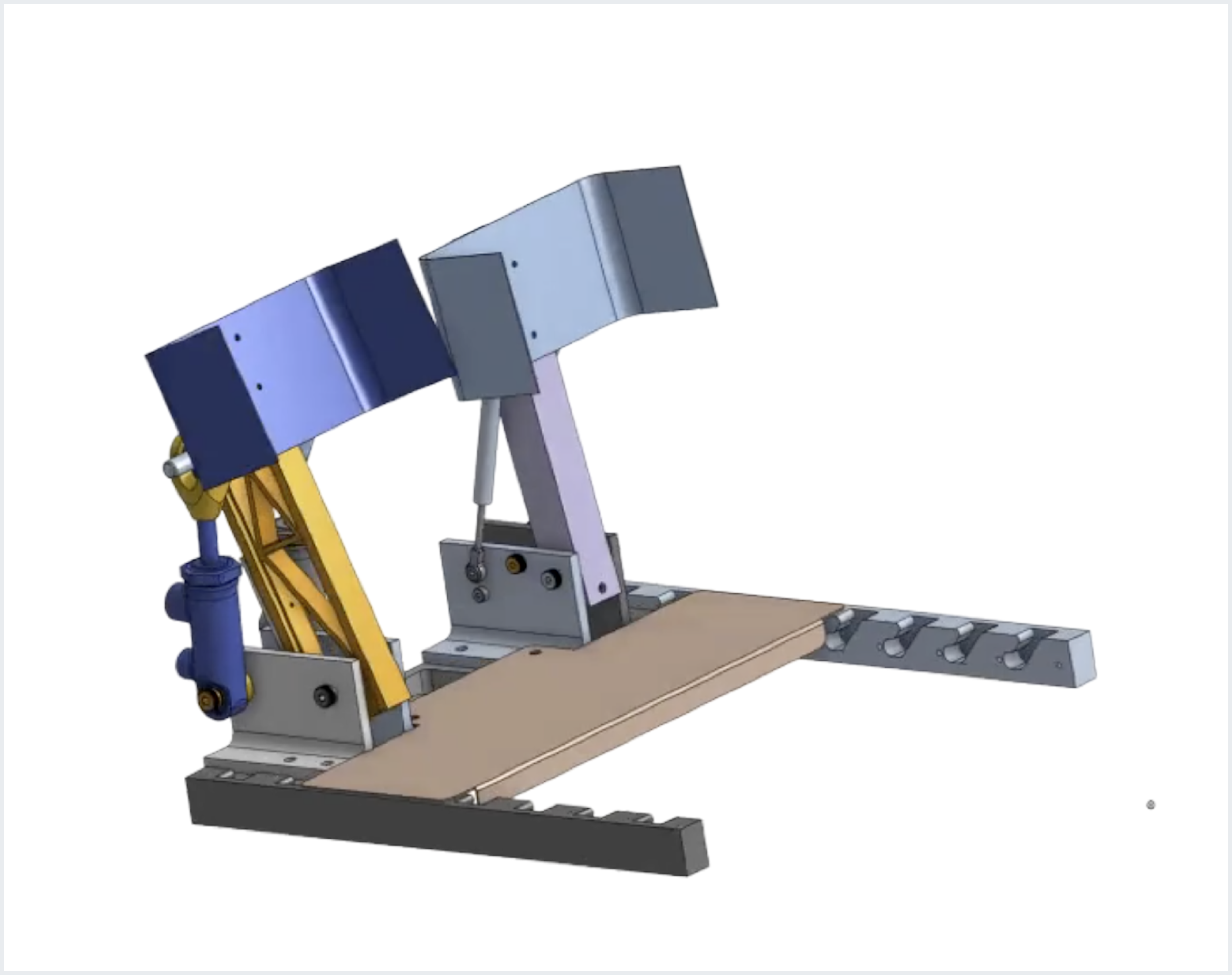
We are working with an orange pedal arm, which is part of a braking and accelerator system. This pedal arm is part of a larger assembly that can be adjusted based on the driver's foot size. It rotates around a central point and is constrained by various features, such as bearings and fasteners.
Display the full assembly with the orange pedal arm highlighted to show how it fits within the larger system.
Step 2: Isolating the Part for Focus
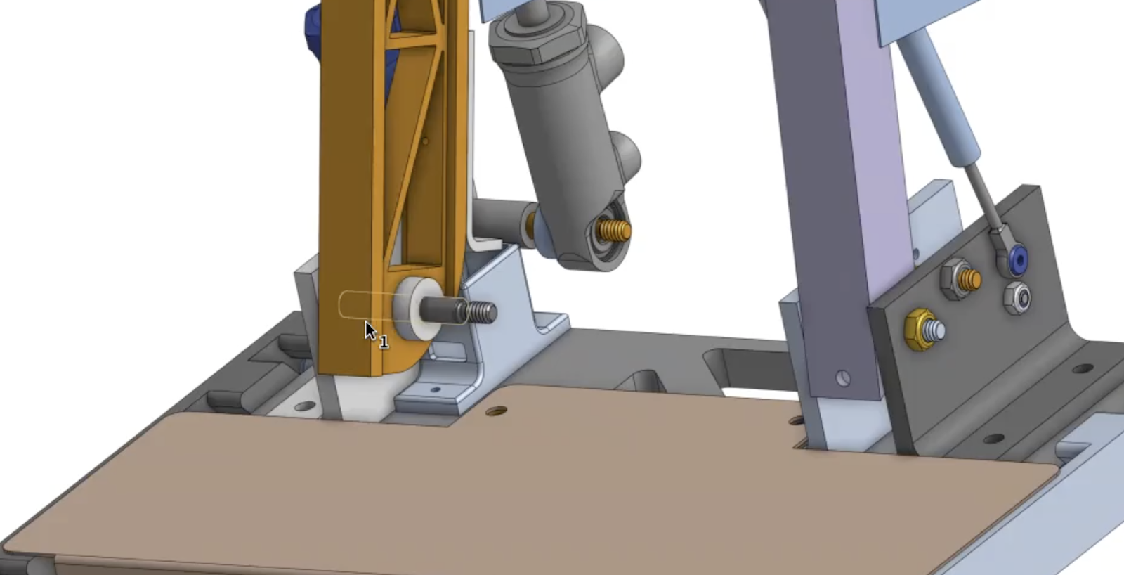
To better understand the part, we'll hide the surrounding components and focus only on the orange arm. This lets us clearly see important features, such as the bearing surface that controls horizontal movement and the hole through which the part rotates. We also see a sensor switch attachment point, which will be important in the drawing.
Step 3: Setting Up the 2D Drawing
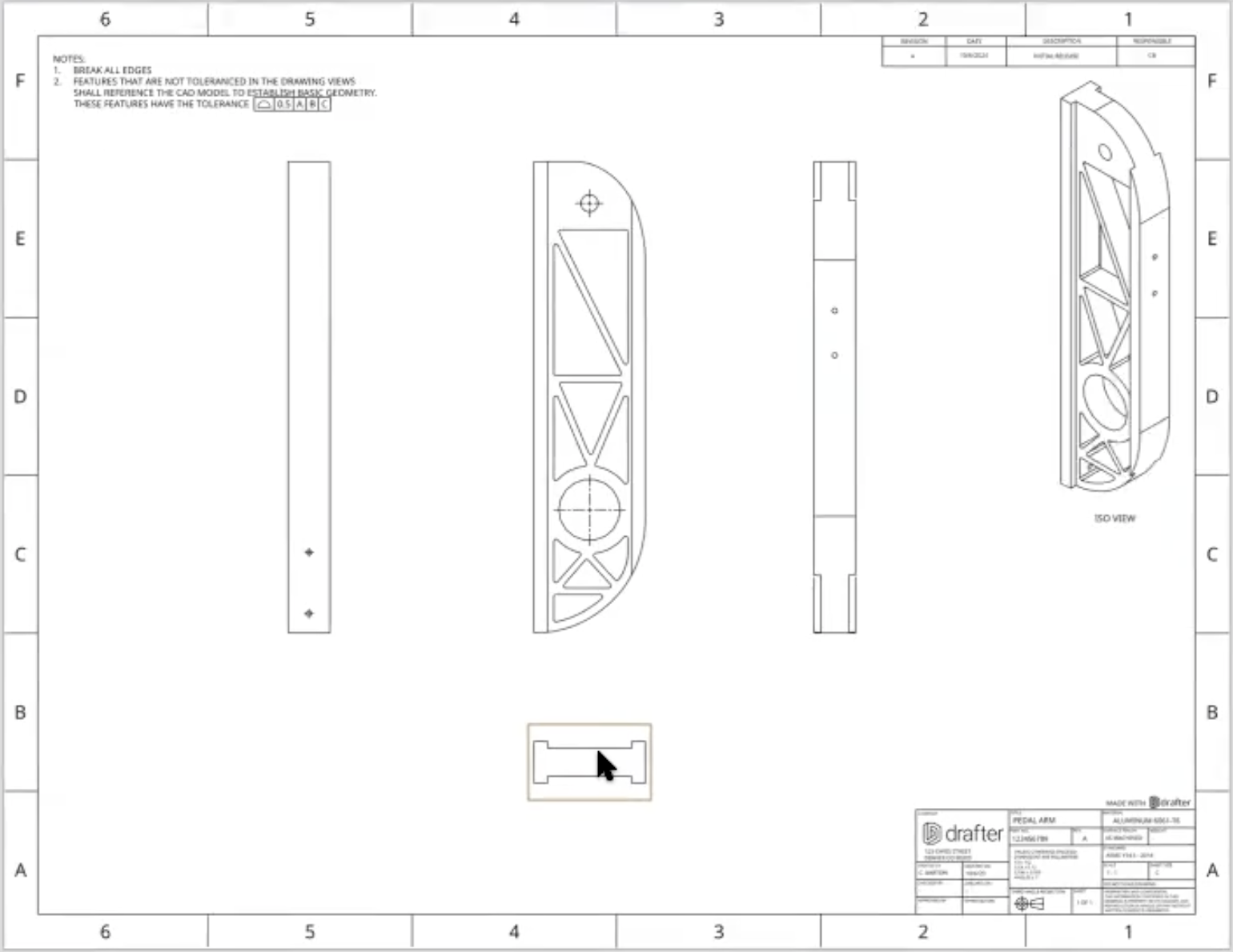
Now, we begin creating the 2D drawing by placing essential views. These views help us visualize the part from different angles. We’ll start with an isometric view, which shows the part in 3D, to give an overview of its shape and structure. This view is placed in the upper corner, along with a title block that we'll update with key information.
To capture all critical features of the part, we need multiple views. We’ll add top, side, and other views to highlight important features like the holes on either side of the arm.These views are crucial for clearly communicating the size, shape, and features of the part in 2D.
Step 4: Filling in the Title Block
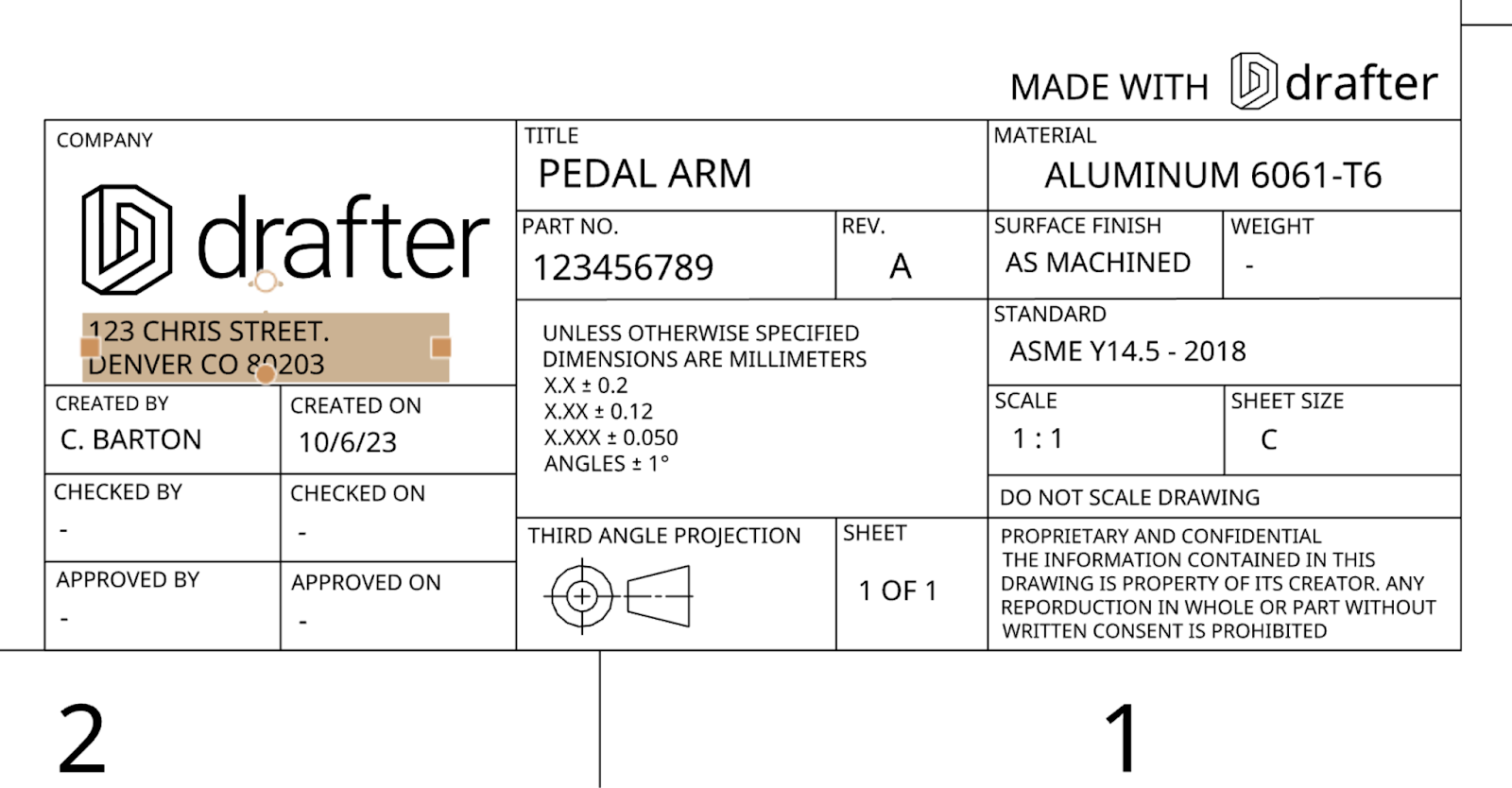
The title block contains important information about the part and the company making it. We’ll add details like the company name, logo, part number, revision (in this case, "A"), material (6061 aluminum), and the designer's name. This helps ensure everyone using the drawing knows who created the part and important details about it.
Step 5: Establishing Datums for Reference
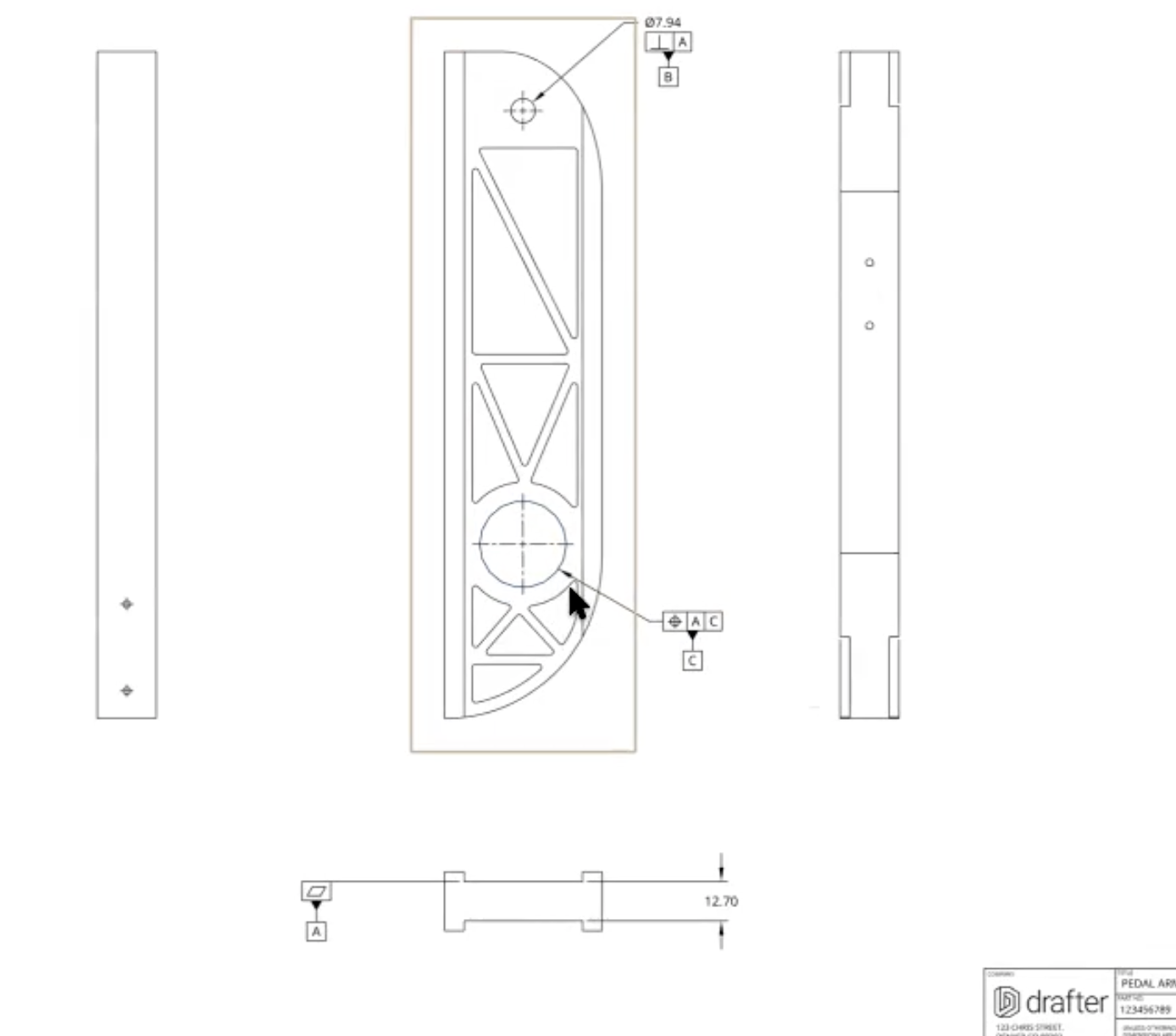
In GD&T, datums are reference points or surfaces that we use to control how the part is measured and assembled. We'll assign our first datum, A, to the top surface of the part because it’s flat and stable. Datum B will be the main hole where the part rotates, and Datum C will be another important hole used for positioning. These datums will help us define how the part is constrained in the assembly.
Step 6: Identifying Critical Features and Applying Tolerances
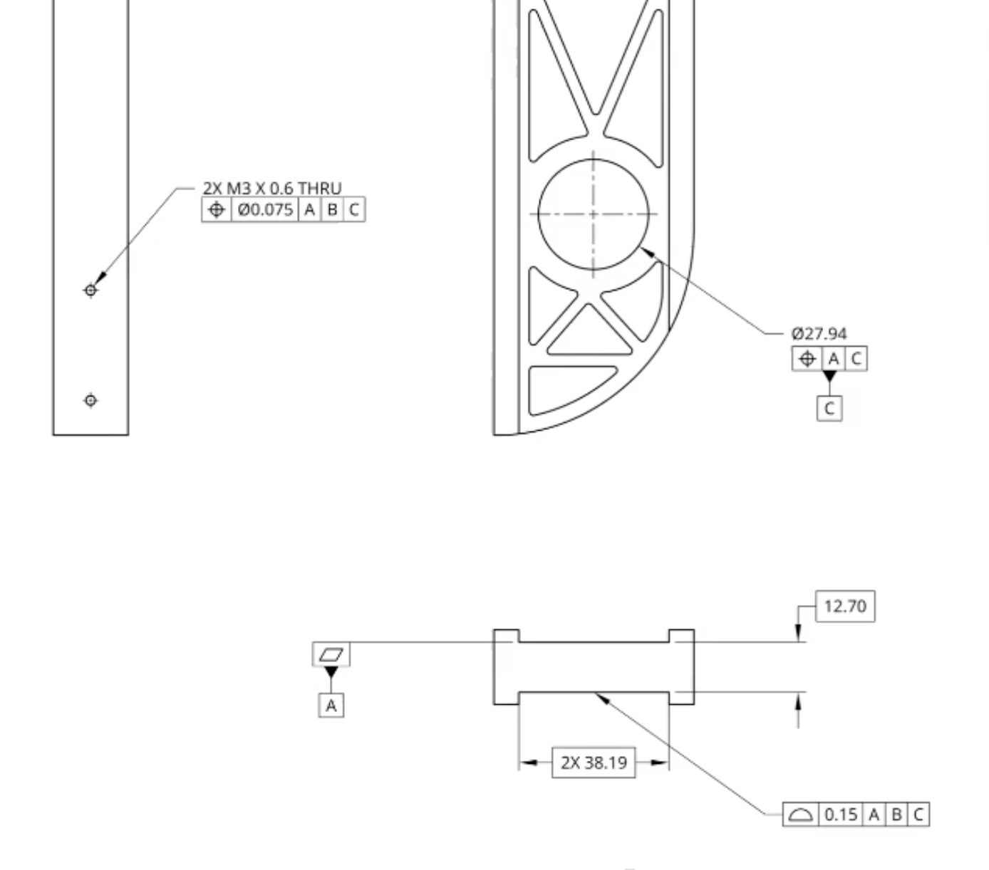
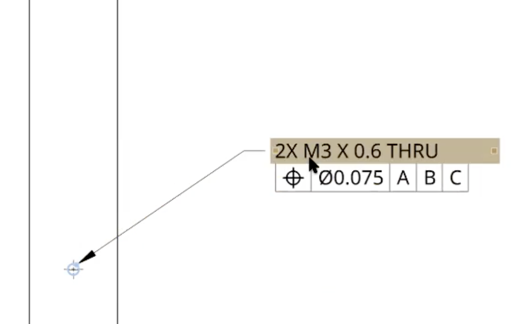
Now, we’ll focus on the most important features of the part. These include the holes for fasteners and the overall width of the part. For each critical feature, we apply tolerances that specify how much variation is allowed in their size or position. For example, we’ll apply a position tolerance to the holes, which ensures they are located accurately relative to the datums.
Step 7: Defining all non-CAD related Critical Information
This could include surface finish, threaded holes, part marking and more. The part has threaded holes for fasteners. We need to specify the correct thread size, which in this case is M3 x 0.6. This notation means the hole is for a 3mm diameter screw with a 0.6mm thread pitch. We also indicate that the hole is drilled completely through the part, ensuring the fastener fits all the way.
Step 8: Controlling the Overall Size and Shape
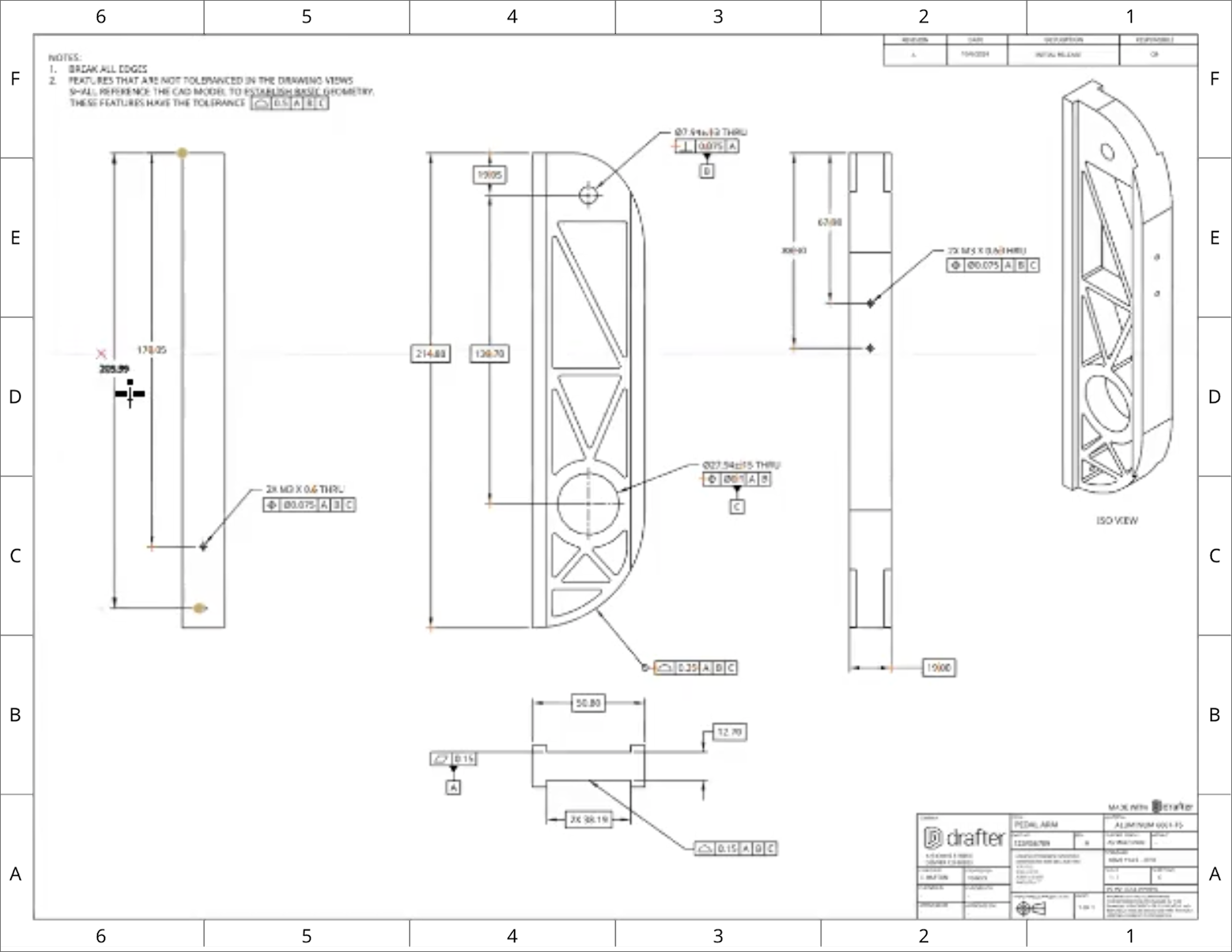
Beyond the holes, we need to control the overall size and shape of the part. For this, we’ll apply a profile tolerance to ensure the width and other important surfaces stay within acceptable limits. This profile tolerance will help control the form of the part, making sure it fits properly when assembled with other components.
Step 9: Adding General Notes
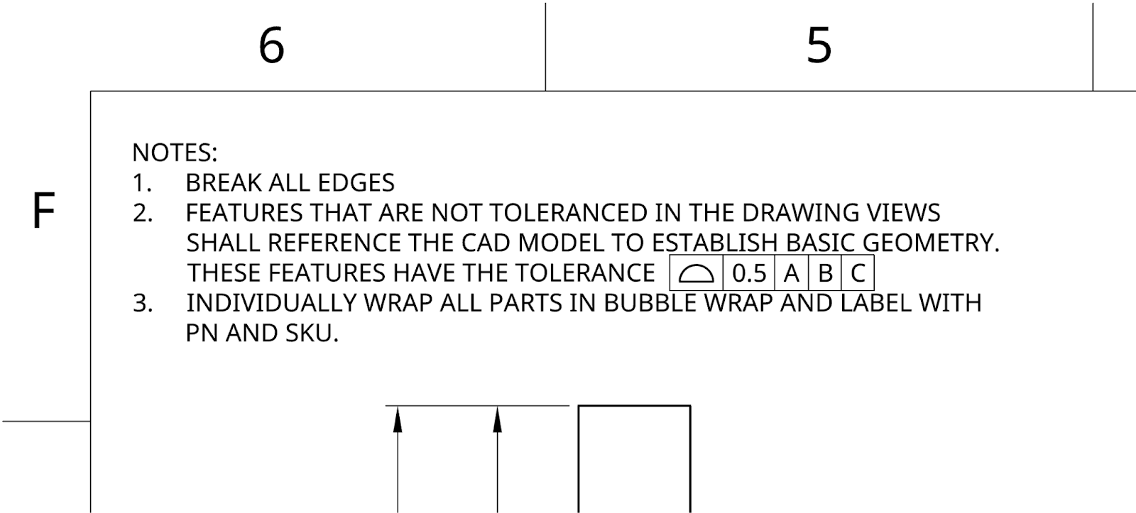
In most technical drawings, notes are an essential part of the communication. Notes can clarify details that aren’t covered by the dimensions or GD&T symbols. For example, you might include instructions on surface finish, special assembly requirements, or any additional information about the part that could be useful to the manufacturer or the assembler. Notes can also specify general tolerances for features that aren’t explicitly dimensioned.
Step 10: Reviewing the Complete Drawing
Finally, we review the drawing to make sure all the key features are clearly defined. This includes verifying the datums, critical features, and tolerances. We ensure that everything is dimensioned correctly, that all the necessary information is in the title block, and that the part is fully defined according to GD&T standards. At this stage, the drawing should be ready for use in manufacturing.
Show the completed 2D drawing with all datums, tolerances, views, and critical features clearly defined.

